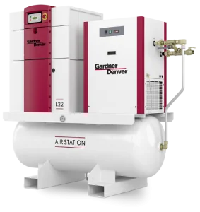
 The Role of Your Compressor
Most of us know how important location is in retail business. Although location when it comes to support equipment is just as crucial if not more so.
Support equipment, pumps, blowers, and air compressors more often than not are put where an existing one was, and this is not always best. Many factors in today’s modern equipment era should be observed and considered.
Let’s take an air compressor for example, over the years the majority are put in mechanical rooms with little or no ventilation and sometimes, with other heat generating equipment. Considering that an air cooled rotary screw runs 100% above Ambient when it's BRAND new, shouldn’t we try and give the compressor as much fresh cool, dry air to compress as possible?
A safe idea is outside and under roof but let’s take this to the next step and say the north eastern side of the facility if possible. 100% over our normal temperatures here in the south doesn’t give us much of a band when normal shut downs are 225 degrees. That’s why we don’t want that eye in the sky “Sun” baking on our unit all afternoon.Not to mention how direct sunlight can fade controller faces and eventually render them unreadable.
Now if we can’t go outside, let’s make sure the inside location is still cool, dry and has adequate ventilation, preferably to the outside. An outside wall to exhaust our heat would be a great idea, this is important so that we don’t recycle our heated air off of our cooler back to compression. A good idea for our intake and exhaust is to draw from outside or intake and, blow-exhaust to the outdoors as well.
There are many variables that should be considered when installing a new piece of support equipment the better decisions we make now, can save a lot of headaches later.
Give us a call and let us help make sure you put your equipment in the right location for optimum performance.
Two common descriptions of pump pressure are PSI (pounds per square inch) and TDH (total dynamic head). PSI is usually associated with positive displacement pumps and TDH with centrifugal pumps, but the terms are interchangeable.
PSI is usually stated in gauge pressure as PSIG, the pressure you read on a pressure gauge. Negative pressure is usually stated in inches of mercury vacuum, HgV. These are common values used in America, but pressure can be translated into metric and other terms.
Differential pressure (ΔP or delta P or DP) is the difference in pressure across the pump. Differential pressure is used for pump and motor selection as it is the actual pressure the pump sees. DP is the pressure on the suction side of the pump plus the pressure on the discharge side of the pump in relation to the desired discharge pressure. If 50PSI is the desired discharge pressure and you have +10PSI on the suction side, the pump needs to develop 40PSI for the total discharge pressure to equal 50PSI (+10+40). Likewise, if the suction pressure was negative -5PSI (~10”HgV) such as a suction lift application where the liquid level is below the pump, the pump would have to develop 55PSI (-5+55) to achieve the total discharge pressure of 50PSI.
PSIA is pressure per square inch absolute. This takes into account atmospheric pressure. 0PSIG is equal to 14.7PSIA at sea level or 33.9’ of water column (atmospheric pressure decreases with altitude, for example: 14.2PSIA at 1000 ft. elevation).
TDH or total dynamic head is another common term for describing pressure across a pump. Every 2.31’ of vertical level = 1 PSI for water and liquids with a specific gravity of 1 (or 8.34 pounds per gallon). For liquids heavier than water, the pressure exerted is greater for the same vertical level. For example; a tank with 23.1’ of water level would read 10PSI on a pressure gauge at the bottom of the tank [(23.1ft./2.31ft/psi)X1SG=10psi].
With a liquid with a specific gravity of 1.2 (10 pounds per gallon) at the same 23.1 foot level, the pressure gauge would read 12PSI [(23.1ft./2.31ft/psi)X1.2SG=12psi].
And a pressure gauge would read less for liquids lighter than water.
Read on for more information on PSI vs. PSIG.
The pump manufacturer will state the NPSHr, Net Positive Suction Head required, to prevent cavitation or vaporization of the liquid in the pump. The NPSHa, Net Positive Suction Head available, must be greater than that required by the pump.
For a basic understanding of Net Positive Suction Head, you must think in terms of absolute pressure in feet. To determine the NPSHa, the Net Positive Suction Head available at the pump inlet, you first determine the pressure above the liquid. As atmospheric pressure varies with altitude (and weather), the site elevation must be known. For this discussion, we will be at sea level and pumping water.
At zero feet elevation, sea level, the atmospheric pressure is 33.9’ absolute (or 14.7psia). When you are pumping from a tank that is open to atmosphere, you automatically have 33.9’ absolute pressure helping you get liquid to the pump suction.
We will assume our tank has 10 feet of cold water level above the pump. We have a total of 43.9’ of pressure available above the pump (33.9’ atmos. pressure + 10’ liquid level).
That 33.9’ of atmospheric pressure is reduced first by the vapor pressure of the liquid (vapor pressure is the tendency for the liquid to become a vapor).
Using water as a common reference. At 33°F., the vapor pressure of water is basically zero. As the water temperature increases, so does its vapor pressure. At 212°F, the vapor pressure equals 33.9’, the point at which water turns to a vapor.
If we heat our water tank example to 212°F, the atmospheric pressure of 33.9’ minus the vapor pressure of 33.9’ leaves us with only the 10’ of liquid level to supply the pump.
The last part of the equation is deducting the friction loss of the suction piping. This calculation will vary from application to application.
Net Positive Suction Head Available = pressure above the liquid + liquid level above the pump (negative if level is below the pump) – the vapor pressure of liquid at pumping temperature – the friction loss of the suction piping.
Although NPSH calculations are not exact, they but must be considered for proper pump selection.
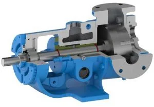 Getting The Most Out of Your Viking Abrasive liquid pumps
Pumping abrasive liquids are always a difficult application. The hardness and percentage of solids increase the wear in the pump and piping. Pump speed and pressure directly affect pump wear. Pump speed can be addressed by oversizing the pump to reduce the RPM of the pumping elements. This lessens the abrasion effect and the NPSH required to prevent cavitation. The suction side of the pump should be oversized to ensure a positive flow to the pump. Oversized strainers also reduce suction side pressure drop and protect the pump from foreign objects.
Reducing the discharge pressure is most effective way to increase pump life. Reducing the discharge pressure is entirely in the design of the piping system downstream of the pump. Enlarged piping, flow meters, heat exchangers, etc. all help to reduce liquid velocities and lower the friction losses that the pump has to overcome to get the fluid to the discharge point.
Most pumps that have been in abrasive service for any length of time are worn to the point that the rebuild cost exceeds that of a replacement pump. The pump is required to be a sacrificial component in these services by necessity. After all the piping system improvements have been made, there are several ways to maximize the pump life. We start with the Abrasive Liquid pump with hardened steel gears and the standard Tungsten Carbide Idler Pin and Bushing.
One of the more common applications is metering a filled viscous liquid to maintain a precise flow rate. It is essential that the pump be operated on variable speed drive. The motor must be oversized to allow cooling at low RPMs and sufficient torque at higher speeds. A gear ratio is selected to provide the desired flow rate at a low motor speed, for this example; 33% of rated RPM or 20Hz (the lower the better). As the pump wears, the VFD will increase the pump speed to maintain its flow meter set point. As the motor speed approaches a predetermined speed for the system, for example; 85% of rated RPM or 51Hz; during a shutdown the thrust bearing is adjusted in place, reducing the rotor end clearance to compensate for wear. When the system is re-started, the VFD will operate at a lower speed, perhaps 30-35 Hz, to maintain the flow meter set point. The next time the pump speed may get to 60Hz before the next end clearance adjustment is made. Most modern motors can operate at 88-90Hz without any problems, inverter-duty can go higher. Most VFDs can go to 120Hz with some even higher. Operating above 60Hz varies from a personal preference to plant management establishing limits. So check what is standard or allowed in your facility or inherent in the system design and programming. Precautions are to be considered in motor selection as horsepower drops off proportionately with motor RPM below 60Hz and torque drops off proportionately above 60Hz. The pump manufacturer publishes a maximum pump RPM for a given viscosity to prevent cavitation, not to be exceeded, this can be translated into a maximum operating hertz for a given pump size, to be compensated for based on system design and customer experience. A half worn out pump cost the same to replace as a fully worn out pump.
Some systems require constant recirculation to prevent the solids from settling out. To extend pump life, the recirculation loop should be designed with minimal back pressure and operate at the lowest RPM required to keep the solids in suspension.
In critical applications, or highly abrasive filler applications, or to have the minimal downtime, the interior surfaces of the pump can be hard coated with an abrasion resistant material to increase pump life to its maximum.