 Getting The Most Out of Your Viking Abrasive liquid pumps
Pumping abrasive liquids are always a difficult application. The hardness and percentage of solids increase the wear in the pump and piping. Pump speed and pressure directly affect pump wear. Pump speed can be addressed by oversizing the pump to reduce the RPM of the pumping elements. This lessens the abrasion effect and the NPSH required to prevent cavitation. The suction side of the pump should be oversized to ensure a positive flow to the pump. Oversized strainers also reduce suction side pressure drop and protect the pump from foreign objects.
Reducing the discharge pressure is most effective way to increase pump life. Reducing the discharge pressure is entirely in the design of the piping system downstream of the pump. Enlarged piping, flow meters, heat exchangers, etc. all help to reduce liquid velocities and lower the friction losses that the pump has to overcome to get the fluid to the discharge point.
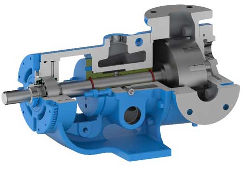
Most pumps that have been in abrasive service for any length of time are worn to the point that the rebuild cost exceeds that of a replacement pump. The pump is required to be a sacrificial component in these services by necessity. After all the piping system improvements have been made, there are several ways to maximize the pump life. We start with the Abrasive Liquid pump with hardened steel gears and the standard Tungsten Carbide Idler Pin and Bushing.
One of the more common applications is metering a filled viscous liquid to maintain a precise flow rate. It is essential that the pump be operated on variable speed drive. The motor must be oversized to allow cooling at low RPMs and sufficient torque at higher speeds. A gear ratio is selected to provide the desired flow rate at a low motor speed, for this example; 33% of rated RPM or 20Hz (the lower the better). As the pump wears, the VFD will increase the pump speed to maintain its flow meter set point. As the motor speed approaches a predetermined speed for the system, for example; 85% of rated RPM or 51Hz; during a shutdown the thrust bearing is adjusted in place, reducing the rotor end clearance to compensate for wear. When the system is re-started, the VFD will operate at a lower speed, perhaps 30-35 Hz, to maintain the flow meter set point. The next time the pump speed may get to 60Hz before the next end clearance adjustment is made. Most modern motors can operate at 88-90Hz without any problems, inverter-duty can go higher. Most VFDs can go to 120Hz with some even higher. Operating above 60Hz varies from a personal preference to plant management establishing limits. So check what is standard or allowed in your facility or inherent in the system design and programming. Precautions are to be considered in motor selection as horsepower drops off proportionately with motor RPM below 60Hz and torque drops off proportionately above 60Hz. The pump manufacturer publishes a maximum pump RPM for a given viscosity to prevent cavitation, not to be exceeded, this can be translated into a maximum operating hertz for a given pump size, to be compensated for based on system design and customer experience. A half worn out pump cost the same to replace as a fully worn out pump.
Some systems require constant recirculation to prevent the solids from settling out. To extend pump life, the recirculation loop should be designed with minimal back pressure and operate at the lowest RPM required to keep the solids in suspension.
In critical applications, or highly abrasive filler applications, or to have the minimal downtime, the interior surfaces of the pump can be hard coated with an abrasion resistant material to increase pump life to its maximum.


